- Training and Education
- How to Improve Denitrification
- How to Improve Phosphorus Removal
- Avoid Mistakes
- Publications 1 - Banff Sludge Tank Mixer
- Publication 2 - Innovative Mixing Technology
- Publication 3 - Troubleshooting Water and Wastewater Mixing Problems
Training & Education for Optimal System Performance
We offer comprehensive training and education to ensure your system operates at peak efficiency.
✅ Onsite Training – Hands-on guidance tailored to your specific system and process.
✅ Online Training – Flexible, expert-led sessions for remote learning and support.
📞 Call us today to discuss how we can help you maximize your system’s performance!
How to Improve Denitrification Performance?
Denitrification efficiency is highly sensitive to dissolved oxygen (DO) levels. Even a low DO concentration of 0.2 mg·L⁻¹ can reduce the denitrification rate by up to 40% [1]. Research has shown that inhibition can occur at even lower DO levels, with 0.09 mg·L⁻¹ causing a 35% reduction [2].
✅ Maintain True Anoxic Conditions
Denitrification occurs in an oxygen-depleted environment. The presence of even minimal DO levels can hinder the process by disrupting microbial respiration.
✅ Optimized Mixing with HPCD-X
Our HPCD-X mixer is specifically designed for oxygen-sensitive processes, ensuring:
🔹 No vortex formation – Prevents air drawdown into the liquid.
🔹 Minimal surface disturbance – Keeps the water column stratified, preserving anoxic conditions.
🔹 Enhanced nitrogen and phosphorus removal – Creates the ideal flow for process efficiency.
🎥 Watch the Full-Scale Mixing Video
This video, taken by our client, showcases the HPCD-X in action. Notice the quiet water surface, free from vortex formation, demonstrating superior anoxic mixing performance.
Massimo Raboni 1, Vincenzo Torretta 1,*, Paolo Viotti 2 and Giordano Urbini. Pilot Experimentation with Complete Mixing Anoxic Reactors to Improve Sewage Denitrification in Treatment Plants in Small Communities. Sustainability 2014, 6, 112-122; doi:10.3390/su6010112
Dawson, R.N.; Murphy, K.L. The temperature dependency of biological denitrification. Water Res. 1972, 6, 71–83.
1. Metcalf & Eddy, Inc.; Tchobanoglous, G.; Burton, F.L.; Stensel, H.D. Wastewater Engineering: Treatment and Reuse, 4th ed.; McGraw-Hill Education: New York, NY, USA, 2003.
2. Oh, J.; Silverstein, J. Oxygen inhibition of activated sludge denitrification. Water Res. 1999, 33, 1925–1937.
3. Rössle, W.H.; Pretorius, W.A. A review of characterization requirements for in-line prefermenters Paper 1: Wastewater characterization. Water SA 2001, 27, 405–412.
How to Improve Phosphorus Removal?
Maintaining a strict anaerobic environment is essential for effective phosphorus removal in biological nutrient removal (BNR) processes. Even minimal oxygen presence in the anaerobic reactor can disrupt phosphorus-accumulating organisms (PAOs) and reduce efficiency.
✅ Why is Oxygen Undesirable?
When DO enters the anaerobic zone, it causes:
🔹 Inhibition of rbCOD fragmentation – Prevents the formation of acetic and propionic acid, which are essential for PAO metabolism.
🔹 Unintended electron acceptor availability – PAOs and competing organisms will consume volatile fatty acids (VFAs) instead of storing them for phosphorus uptake, reducing removal efficiency.
✅ Optimized Mixing with HPCD-X
Our HPCD-X mixer is specifically designed for oxygen-sensitive applications, ensuring:
🔹 No vortex formation – Prevents unwanted air drawdown.
🔹 Minimal surface disturbance – Maintains true anaerobic conditions.
🔹 Enhanced phosphorus removal – Provides precise flow control for process stability.
📞 Contact us to discuss how HPCD-X can help maximize phosphorus removal efficiency in your treatment process!
Avoid Mixing Mistakes – Choose the Right Technology
Selecting the wrong mixing technology can lead to poor process performance, high energy costs, and frequent maintenance issues. To ensure optimal mixing efficiency, avoid these common mistakes:
✅ Using the Wrong Mixing Technology
Different processes require different mixing approaches. Conventional mixers may not provide the required shear, flow pattern, or energy efficiency needed for advanced industrial applications.
✅ Overmixing or Undermixing
🔹 Overmixing can lead to excessive shear, breaking flocs or damaging biological granules.
🔹 Undermixing can result in dead zones, solids settlement, and inconsistent process performance.
✅ Ignoring Air Drawdown in Anoxic/Anaerobic Processes
Unwanted air entrainment can disrupt oxygen-sensitive processes such as denitrification and phosphorus removal, reducing treatment efficiency.
✅ Neglecting Energy Efficiency
Mixers should be designed to achieve process objectives with minimal energy input. Selecting an energy-efficient mixer can lead to significant operational cost savings.
✅ Failing to Consider Maintenance & Reliability
Frequent maintenance due to ragging, clogging, or impeller wear increases downtime and costs. A well-designed mixer should operate reliably with minimal maintenance.
Publications:
Troubleshooting Water and Wastewater Plant Mixing Equipment Problems. Environment Engineering & Science. December, 2017.
Banff’s Sludge Tank Mixer Improves Performance, Cut Energy, Maintenance Cost. Environment Engineering & Science. August, 2017.
New Mixing Technology Brought Banff WWTP Facility Back to Service
Li Wang
New mixing technology – High Performance Centrifugal Dispersing Impeller (HPCDI) helped Banff wastewater treatment plant solve the solids settlement problem and brought the sludge mixing tank back to service. The new technology also saves more than 80% energy comparing with other mixing products on the market.
The Town of Banff, Alberta, is a unique mountain community located in Canada’s first National Park and UNESCO World Heritage Site. The Town of Banff has been working hard to make its facilities greener and greener. Facilities upgrading with energy efficient equipment is one of the Town’s approaches.
Problems
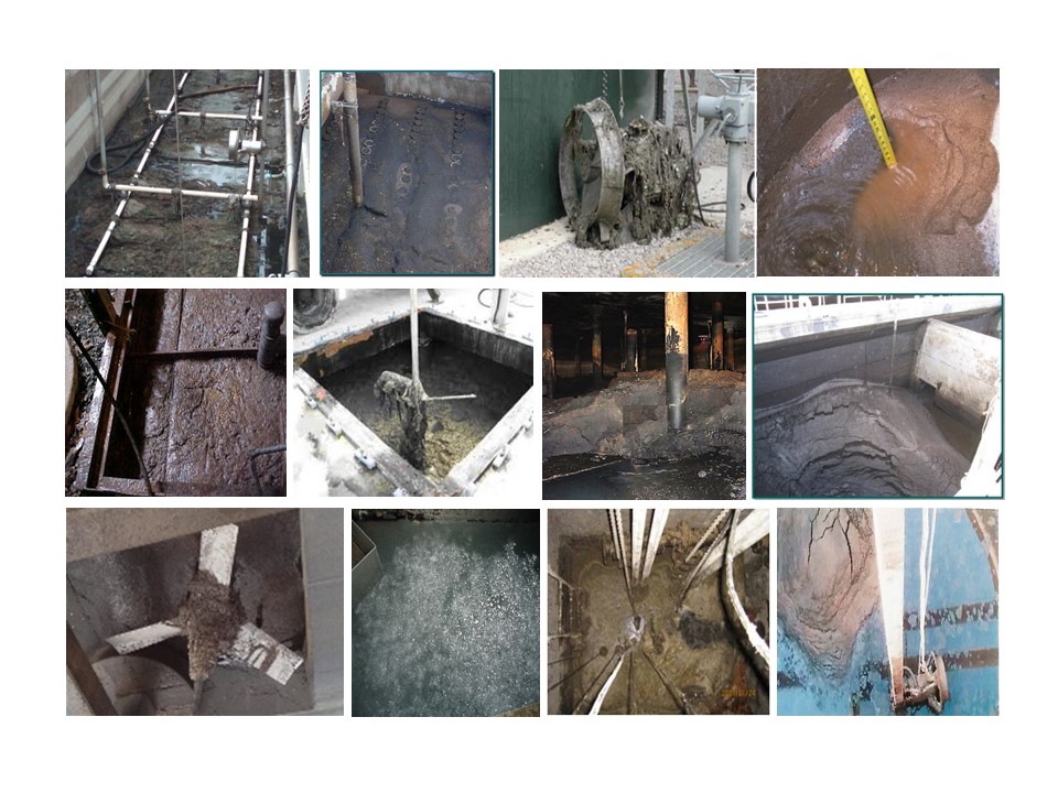
Many municipalities have operation and maintenance problems of solids settlement in their wastewater treatment facilities such as septage receiving tanks, sludge (storage) tanks, fermenters, digesters. Especially those accept sludge from primary clarifiers which normally have certain amount of sand and grit.
The sludge mixing tank at Banff WWTP receives sludge from its primary clarifiers and dissolved air flotation (DAF). Its design function is to mix the received sludge and send the mixed sludge to the fermenters where volatile fatty acid (VFA) is produced for bio-nutrient removal. One 5 kW submersible mixer was originally installed for sludge mixing. However, the mixer had difficulty to keep the solids suspended and there significant amount of solids settled at the tank bottom. The solids settlement problem was so severe that the tank was taken out of service for more than 4 years.
Another concern of the Town is the ragging issues with traditional mixers. Ragging is one of the reasons cause submersible mixer impeller unbalance and seal failures. Leakage to the motor cage further damages the equipment. The Town has experienced frequent submersible mixers overhauls due to motor damages caused by seal failures.
Solution
In 2015, the Town decided to upgrade the facility and brought the tank back to service. To address the solids settling problem, the Town evaluated different mixing technologies available on the market.
Solids settlement has been a problem for a long time and is still a hot studying topic in the industry. Solids suspension requires sufficient upflow in the tank. Solids can only be lifted when the upflow velocity reaches certain value. Traditional submersible mixer pumps liquid forwardly forming a high velocity plume. The velocity anywhere else in the tank is relatively low. Other mixing technologies, such as pitched-blade turbine, propellers and their modifications including hydrofoil (or high efficiency) impellers push liquid downwards, spread radially at the tank bottom, then go upward along the tank side wall.
If the upflow velocity is not high enough, solids will settle at the bottom along the walls. This is not uncommon for facilities with traditional mixers installed. In most cases, to improve the mixing effect, much larger equipment were recommended. The motor power proposed by other mixer suppliers ranges from 3.7 kW to 17 kW.
Dennis Jasinsky, utility supervisor of the Town of Banff, found the HPCDI technology developed by Revolmix as an effective solution to this application. HPCDI applies new concept mixing and different mechanism. Its unique design creates flow pattern best suitable for solids suspension.
HPCDI has superior solids suspension capacity. Unlike conventional mixers pushing water downwards or sometimes upwards, HPCDI lift water toward the impeller with a tornado like swirling movement. At the tank bottom, such swirling movement sweep the solids to the center where they are suspended. Such flow pattern leaves a completely clean tank bottom even at the edge of side wall.
With a number of vanes configured in the impeller, HPCDI pumps more water at relatively low velocity. It provides effective mixing by spreading the solids outwards with centrifugal forces. It disperses rather than mixing. Combined with the large impeller design, HPCDI creates movement of the whole water body in the tank at much even velocity. Without high local turbulence, such flow pattern has significant energy saving.
Results
The HPCDI was installed in 2015. It provides sufficient mixing to the tank with superior solids suspension capability. No sludge build up was observed after two years operation.
The measured power withdraw is about 1.0 kW. It means more than 80% of energy saving comparing to conventional mixing technologies.
Energy saving is just part of the value provided to the plant. There is also a significant Operation and Maintenance saving for the mixer. The client normally pull out the submersible mixer annually doing the cleaning and maintenance. In addition, the plant has to rebuild their submersible mixers every a few years. The HPCDI is a top entry mixer and the only maintenance is the annually oil-change with one operator spending about 20 minutes.
For sludge mixing, it is not uncommon that many mixers have to be removed and cleared, adding significant costs and process downtime. The unique design of HPCDI makes it non-ragging and maintenance free.
An added bonus is that the Town has turned the sludge mixing tank into a production process unit to produce volatile fatty acid (VFA). The HPCDI for Banff was configured to create mixing under the impeller while at the same time with little disturbance to water above the impeller. Such design doesn’t create vortex at the water surface therefore minimizes the air/oxygen drawdown to the liquid. With such performance, the Town of Banff has turn this sludge mixing tank to a fermenter producing VFA for biological nutrient removal. It is estimated about 40~100 kg VFA is produced daily
Innovative Mixing Technology To Solve Operational Problems In Industrial Applications
Li Wang, Revolmix Processing Ltd.*
*Revolmix Processing Ltd. 72 Hawkdale Close NW, Calgary, AB, T3G 3A6, li.wang@revolmixing.com
ABSTRACT
Poor mixing by traditional mixers results in severe operational problems to the industry with substantial cost. High energy consumption, frequent facilities shutdown, solids settlement (in bioreactors, digesters, sludge tanks, etc.), are just a few of the common issues many plants are experiencing. High Performance Centrifugal Dispersing Impeller (HPCDI) is a newly developed mixing technology to solve difficult mixing problems and improve production. It applies completely new mixing concept and different mixing mechanism from traditional products. Industrial installations have evidenced its satisfactory performance on energy saving and solids suspension. For some cases, more than 80% energy saving has been achieved. This article introduces its applications in industrial applications and the significant benefits to the plant operation.
New innovative mixing technology – High Performance Centrifugal Dispersing Impeller (HPCDI) helped Banff wastewater treatment plant solve the solids settlement problem and brought the sludge mixing tank back to service. The new technology also saves more than 80% energy comparing with other mixing products on the market.
INTRODUCTION
Traditional mixing technologies, such as marine propellers, hydrofoil and their modifications are widely used in the industries. They serve the design purposes well for many applications. However there are challenges in both process and operation where traditional mixers have difficulty to perform satisfactorily. Poor mixing has resulted in significant cost to the industries.
Traditional mixers push water at one direction. Marine propeller, like boat propellers, pushes a plume of water horizontally; hydrofoil type of impellers (also called High Efficiency Impellers) pushing water downwards, occasionally upwards. In circular vessels, hydrofoil impellers create vortex if no baffles are installed. The liquid moves like solids-body rotation where little mixing happens. At most cases, or as standard configuration, baffles are installed to break the vortex and direct the horizontal flow to vertical flow intended to improve the mixing.
Many operational issues are caused by improper mixing in the industry. Solids settlement in the vessel is one of them. It reduces active reaction volume and requires costly frequent cleanup. Solids suspension has been a topic studied by many researchers. Current studies are focusing on improving the performance of traditional mixers by optimizing the system design parameters: geometry of the tank, angles of the impeller blades, etc. Without fundamental mixing mechanism changes, the improvement is limited.
High Performance Centrifugal Dispersing Impeller (HPCDI) was developed to solve some of the mixing problems the industry are facing. This article provide brief introduction of the different configuration, mixing concept and mechanism, and performance from traditional mixers.
HPCDI
Configuration
As shown in Figure 1 and Figure 2, different from traditional impellers, HPCDI consists of a round plate and many vanes. Depending on the mixing requirements, the width of each vane and the number of vanes can be changed. The vanes can be configured at different positions: above or below the plate; the outer ends of the vanes can also be configured at various angles, to best suit the applications. Figure 1 HPCDI-G is designed for general purpose mixing. It has strong capacity of surface drawdown as well as bottom liquid lifting. Figure 2 HPCDI –X is for applications where surface drawdown is not desired such as anoxic/anaerobic or other oxygen sensitive reactions.
Flow Pattern
With the installation of baffles in circular vessels, traditional mixers create axial flow or radial flow. Hydrofoil impellers create axial flow and is normally recommended by the industry for solids suspension. When rotated, it discharge flow downwards to the bottom, then spread radially outwards towards the walls. Once it hit the walls, the flow goes upwards directed by the baffles and circles back to the impeller.
Figure 1 HPCDI – G
Figure 2 HPCDI – X
The flow pattern of the typical HPCDI – G, appears completely opposite of that of traditional mixers, is presented in Figure 3 and Figure 4. With the rotation of the impeller, liquid is centrifuged outwards from inner ends to distant ends of each vane. When the liquid is discharged, it creates two low pressure fields: one above the impeller, the other under the impeller. Both fields are replaced by liquid immediately. The rotation of the impeller and the liquid displacement result in two tornado like funnels formed above and under the impeller. The funnel below the plate extends downwards until it touch down to the bottom. The funnel above the plate extends upwards until it reach the liquid surface.
Picture (a) shows the funnel touch down to the bottom and the solids in black color starts to swirl up. Picture (b) shows the fully developed funnel under the impeller. There is another funnel formed above the impeller, mirrored to the black bottom one, with a little vortex at the surface. Picture (c) shows the solids are dispersed outwards and are completed mixer in Picture (d).
Figure 4 provides more details of the liquid motion at the tank bottom as tracked by the solids: solids settled at the bottom were gradually circled to the center of tank bottom under the impeller where they are lifted up by the funnels as shown in Figure 3.
|
(a) (b) (c) (d)
|
Figure 3 Typical Mixing by HPCDI
Unlike traditional mixers often leave some solids pile up along the walls of the vessels, HPCDI leads to the very clean bottom as shown in (d) of Figure 5, even at the periphery of the tank bottom. This is also an indication of no dead or stagnant zone in the tank if mixed by the HPCDI.
|
(a) (b) (c) (d)
|
Figure 4 Bottom Solids Motion
Figure 5 presents the flowlines at steady state, which look like the outlines of two oranges laid one above the other. The flow is spread out and circulated back to the impeller through the two funnels.
There are applications which minimum surface disturb is designed. For instances, air introduction to the liquid for anoxic or anaerobic reactions might jeopardize the process or cause some other unwanted results. Other applications include oxygen or carbon dioxide sensitive reactions. Figure 6 presents the CFD model of the HPCDI designed for such applications. It shows strong bottom lifting motion while little surface movement.
Tornado – Like Solids Suspension
Tornado is known one of the most powerful forces for lifting in nature.
The HPCDI creates flow pattern similar to the tornado. When the HPCDI rotates, liquid is pushed radially outwards from center of the impeller outwards along the vanes, a vacuum field is created. This satisfies the two essential conditions for tornado formation: 1). rapidly rotating fluid 2). a central core of low pressure.
Figure 5 Typical Flow Pattern of HPCDI
Figure 6 Flow Pattern of HPCDI – Anoxic/Anaerobic
Author has noticed, even when the impeller rotates at low speed, the funnel can also be developed and extended downwards till touch down bottom. As long as the funnel touch down the bottom, the solids will be lifted up.
More studies are required to fully understand the solids suspension mechanism by this model. However, the following two factors are easy to understand: 1). the funnel normally has higher velocity, and 2). the solids are lifted up, instead of vertically, at a fairly low angle along with the swirling liquid movement.
Fireworks – Like Dispersion
Mixing is currently defined as reduction of inhomogeneity. Dispersing is to distribute or spread (particles/liquid) over a wide area; go or cause to go in different directions. It implies a wider separation and a complete breaking up of a mass or group. Therefore the disperser should function as the engine in the whole system, drive off the media and circulation back to the impeller.
Dispersing is advanced mixing or high level mixing. In fact, what many industrial applications required are dispersing, rather than mixing, such as miscible liquid blending, polymer dilution, pH adjustment, coagulation, etc. In chemical industry, some fast chemical reactions especially organic reactions, the reactants need be dispersed at high speed to avoid unwanted competitive reactions if high local concentration reactant present. In biological reaction applications, slow dispersing of chemical, will cause severe damage to biomass. Fast dispersion is essential to achieve the process objectives.
Centralized Mixing
As shown in the Figure 5, the flow is energized by the impeller. The liquid in the whole tank is brought to the impeller and then distributed out. This centralized flow pattern together with the dispersing effect make it the near-ideal Continuous Stirred-Tank Reactor (CSTR), especially for high reaction rate applications. The easy modeling of this flow pattern makes industrial scale-up or scale-down much more practical and accurate.
Energy Consumption Analysis
With the installation of baffles in circular vessels, traditional mixers create axial flow or radial flow. Hydrofoil impellers create axial flow and is normally recommended for solids suspension. When rotated, it pumps flow downwards to the bottom, then spread radially outwards towards the walls. Once it hit the walls, the flow goes upwards and recirculated back to the impeller.
Solids suspension by traditional mixers relies on two factors: the turbulence at the bottom and the upflow velocity along the walls. The turbulence created is to keep the solids off the bottom and the upflow is the force eventually lift the solids. Only if the upflow velocity is higher than that of the solids settling velocity, the solids can be moved up. Otherwise, solids pile up at the bottom along the walls.
Comparing to traditional mixers, the HPCDI save energy for the following reasons:
- No baffles are needed.
Baffles are need for traditional mixers to break the vortex and to form the axial flow pattern which was considered suitable for solids suspension. The impeller power number will be increased almost 100% with the installation of baffles for axial impellers (Kevin, Mark and Julian, 2002). This is not difficult to understand: the baffle is to stop the flow momentum so the impeller needs to overcome the resistance from initial state all the time. In another word, it is like driving the car with brakes set all the time.
- Higher solids suspension capability
The author believes, solids suspension follows the Stoke’s Law in which the upflow velocity plays the key role under most circumstances.
Traditional mixers rely on the vertical upflow along the walls to lift the solids. In a mixed vessel, the highest velocity is always under the impeller for down pumping impellers. With the liquid spread away and reaches the side wall, its velocity decreased significantly. Here is the rough calculation: if the D/T (the diameter of impeller over the diameter of Tank) is 0.3, the velocity at the side walls is roughly 11% of the impeller tip speed. Therefore, the solids are carried out to the locations where the upflow velocity is the lowest, for solids suspension.
HPCDI, on the other side, as described, solids will be carried to the bottom center and then they are lifted by the tornado like swirling force where the velocity is the highest. The angled velocity vector provide extra lifting force than the vertical velocity created by traditional mixers.
CASE STUDY
Sludge settlement was not uncommon to many plant operations. The operation spend much considerable time and effort on cleaning solids settled in the lime dissolving tank, fermenters or digesters, or anywhere there is solids present in the water.
At Banff WWTP, there is a sludge mixing tank receiving primary sludge and Dissolved Air Floatation (DAF) sludge. The tank has diameter of 8 m and side water height of 4.5 m. Previously, a 5 kW submersible mixer was installed. Because the primary sludge (from primary clarifiers) contains sand/grit, there was severe solids settlement in the tank (it was once observed about 1.5~1.8 m high sludge settlement along the wall). The tank has been taken out of service for a long time (at least 4 years).
To solve the problem, the same mixer supplier proposed a large product with much larger motor. The Town of Banff also consulted other mixer suppliers including the top entry hydrofoil type and Hyperboloid type. Both mixers require installing baffles to the tank, otherwise the mixers will create vortex with little mixing. The mixer power proposed ranges from 5 kW to 17 kW.
The HPCDI for anoxic reaction as shown in Figure 2 was selected and the measured power withdraw is about 1.0 kW. It is more than 80% of energy saving comparing to traditional mixers.
The HPCDI-Anoxic provides sufficient mixing to the tank, with powerful solids suspension. No sludge build up was observed since installed after one and a half year operation. Most importantly, it doesn’t form vortex at the water surface therefore minimizes the air/oxygen drawdown to the liquid. Currently, the Town of Banff has turn this sludge mixing tank to a fermenter producing volatile fatty acid (VFA) for biological nutrient removal. It is estimated about 40~100 kg VFA is produced daily
CONCLUSION
The HPCDI is a new member to the mixing family. It creates different flow patterns from traditional mixers with tornado like solids suspension and fireworks like dispersion.
Its unique configuration and mixing mechanism result in significant energy saving and mixing efficient improvement.
The industrial installations evidenced its capability to solve mixing problems such as solids suspension.
ACKNOWLEDGEMENT
The authors would like to thank Albert Innovates Technology Future (AITF) for financial support on Intellectual Property protection.
LITERATURE CITED
Kevin J. Myers, Mark F. Reeder and Julian B. Fasano. 2002, Optimize Mixing by using the Proper Baffles. Chemical Engineering Progress, 2, pp. 42-47.
Innovative Mixing Technology To Solve Operational Problems In Industrial Applications
Li Wang, Revolmix Processing Ltd.*